
Building tall in LEGO means nothing unless the thing stands up. That sounds obvious until you're fourteen floors into an 11-story pagoda and a section starts bowing under its own weight. Most builders treat structure as an afterthought, decorating first and hoping the framework holds. After twenty-five years of builds, I can tell you that approach fails at scale. The IMS Pagoda at 1:38 scale is roughly four feet tall with distributed load across all eleven floors. That's not a display piece anymore, that's engineering work. Real gravity applies, and brick calculus requires actual planning.
This project forced me to think in terms of stress points and load paths the way a structural engineer would. Steel bead chains and reinforced cores became as important as the facades themselves. The difference between a MOC that lasts and one that sags into permanent mediocrity comes down to how seriously you take the skeleton before you hang the skin. Everything visible in the final build only works because the invisible framework was designed first, load-tested in my head, and built with deliberate rigidity in mind.
Stand at the base of the IMS Pagoda on race morning and look up. Eleven stories of steel and glass rise above the pit lane, the tallest permanent structure at Indianapolis Motor Speedway. The glass facades catch the early light, the observation decks cantilever outward at various levels, and the whole thing looks like it might be lighter than it actually is. That is what good structural engineering does - it hides the effort. But behind every one of those glass panels is a steel column or beam doing the quiet work of holding everything above it in place.
When I decided to build the Pagoda at 1:38 scale, I knew the structure would need to work the same way. Not symbolically. Functionally. Eleven stories of LEGO is not a cosmetic challenge - it is a physics challenge. Every floor has mass. Every connection has a tolerance. Every column either carries load or it does not. And if the columns do not line up from the ground floor to the roof, the whole thing will lean, bow, or simply collapse under its own weight.
So before I built a single upper floor, I planned the steel bones.
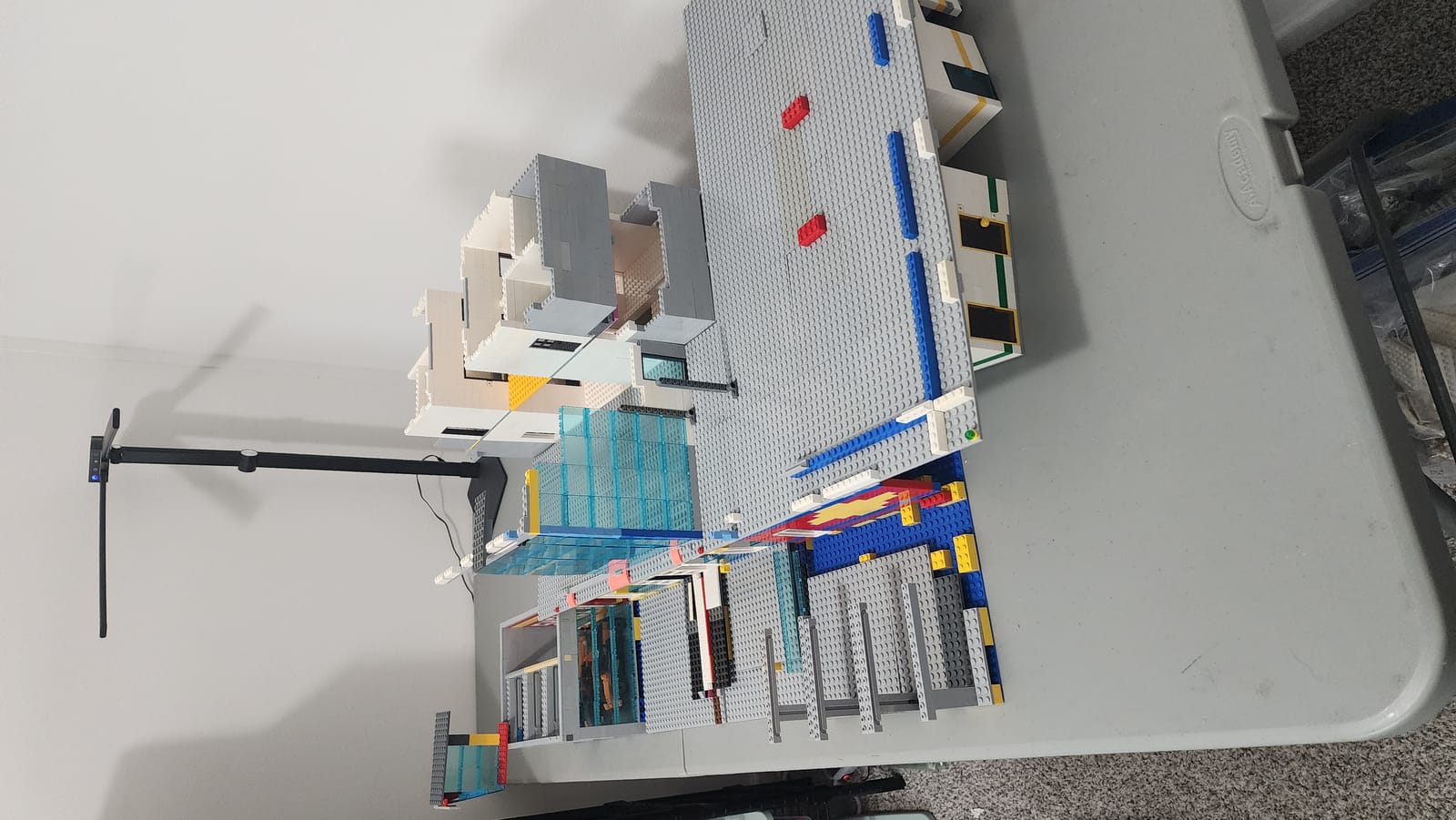
The steel beam locations are visible from above - each one marking where upper floor weight will be supported through the structure.
What you see in that photo is the ground floor of the Pagoda from a top-down angle. The dark elements running through the floor plate are not decorative. They represent the structural steel columns that exist in the real building, and in the LEGO model they serve the exact same purpose - transferring load from every floor above down through the structure and into the base. Twenty-six years of attending the Indianapolis 500 means I have walked around, through, and past this building hundreds of times. I know where the columns are because I have leaned against them waiting for the gates to open. That familiarity is the kind of reference no photograph can replace.
The real IMS Pagoda is a steel frame building. That means its primary structure is a grid of vertical steel columns connected by horizontal steel beams at each floor level. The columns carry compressive loads - the weight of everything above them pushing straight down. The beams carry the floor loads laterally to the columns. Together, they form a rigid frame that resists both gravity and wind. The glass curtain walls you see from the outside are not structural at all - they are just weather barriers hung on the steel skeleton like a jacket on a coat rack.
In real construction, the column spacing is determined by the building's use. The Pagoda has large open interior spaces for hospitality suites, media centers, and observation areas. That means the columns are spaced relatively far apart to minimize obstructions. The structural engineer calculates the loads, sizes the columns, and spaces them so that the beams spanning between them do not deflect more than an acceptable amount. Too far apart and the beams sag. Too close together and the interior becomes a forest of columns.
In LEGO, the same logic applies, just with different materials. Instead of steel I-beams, I am using Technic beams and axles. Instead of welded connections, I am using pin joints and friction fits. Instead of a concrete foundation, I have a layered base plate assembly. But the fundamental principle is identical: create continuous vertical load paths from the top of the building to the bottom, spaced at intervals that allow the horizontal floor plates to span between them without excessive deflection.
A load path is a continuous route that force follows from the point of application to the foundation. In a building, the load path goes: roof to top-floor beams, beams to columns, columns down through every floor to the foundation. Break that path at any point and the structure fails at that point.
The LEGO version of a load path is a stack of bricks, plates, or Technic elements that maintains contact from the top module all the way down to the base. If a column on floor seven does not align with the column on floor six, the load has nowhere to go. It transfers into the floor plate laterally, which means the floor plate is now carrying a load it was not designed for. In LEGO terms, that means a plate starts bowing, a connection pops loose, or the whole floor tilts. The fix is the same as in real engineering: plan your columns first and build everything else around them.
Here is something most people do not consider until they try it: LEGO is heavy in volume. A single 2x4 brick weighs about 2.5 grams. That is nothing. But a floor module for the Pagoda - with a floor plate, perimeter walls, interior partition walls, transparent panel facades, interior details, and structural columns - weighs considerably more. Multiply that by eleven and you are stacking real mass on the bottom floors.
The bottom floor does not just support its own weight. It supports the cumulative weight of every floor above it. Floor one carries floors two through eleven. Floor two carries three through eleven. And so on. This is why skyscrapers have larger columns at the base than at the top - the loads accumulate as you go down. In the LEGO model, I cannot make the bottom columns physically thicker without changing the scale appearance, but I can make sure they are positioned correctly and connected solidly so the load transfers cleanly.
Without structural planning, the failure modes are predictable. The bottom floor plate bows under accumulated weight, creating a visible sag in the middle of the building. Pin connections at the modular separation points loosen because lateral forces from misaligned columns push the pins sideways instead of straight down. Wall sections pop off because the slight lean of an unsupported span puts tension on connections that were designed for compression. I have seen all of these failures in earlier builds, and every one of them traces back to the same root cause: the builder started stacking floors without first establishing where the columns go.
For the Pagoda, I planned the beam positions before designing a single upper floor. The ground floor was built around the structural grid, not the other way around. The columns dictated the floor plan. The floor plan did not dictate the columns. That sequence - structure first, architecture second - is how real buildings get designed, and it is how this model had to be built.
At 1:38 scale, every dimension in the model corresponds to a real dimension on the actual Pagoda. The column spacing is no exception. I did not guess where to put the columns. I derived their positions from the same photo reference process described in Part 4: Ground Floor Footprint - using multiple reference images taken from different angles to triangulate the position of structural elements that are visible through the building's glass facades.
The Pagoda's glass curtain walls are a structural engineer's gift to a model builder. Because the walls are transparent, you can see the columns behind them in photographs. Not always clearly, and not always from every angle, but if you collect enough reference images - and after 26 years of race weekends, I have hundreds - you can map the column grid with reasonable accuracy. The columns appear as dark vertical lines behind the glass, spaced at regular intervals. Where a column meets a floor beam, you see a slightly wider dark area. Where two facades meet at a corner, you can sometimes see the corner column clearly.
I mapped these positions onto the model's floor plan at 1:38 scale. The column spacing in studs had to be close enough to support the floor spans while also matching the visual rhythm visible in the reference photos. In a few places, I adjusted spacing by one stud to align with LEGO's modular geometry - you cannot place a column at 7.3 studs from the corner, so it goes at 7 or 8. Those small compromises are invisible at this scale, but they matter structurally because they determine whether the Technic beams spanning between columns are in tension, compression, or bending at each connection point.
The result is a column grid that looks right from the outside and works right on the inside. The columns are visible through the transparent panels in the model just as they are visible through the glass on the real building. They are part of the visual language of the structure - not hidden, not celebrated, just present. Doing their job.
The IMS Pagoda model uses a modular floor separation system described in Part 2: Modular Design. Each floor lifts off independently for interior access, photography, and maintenance. This modularity is essential for a build this size - you cannot reach the interior of floor six if floors seven through eleven are permanently attached on top of it. But modularity creates a structural challenge: every separation point is a potential weak point in the load path.
The steel bone columns solve this problem. Each column position has a corresponding connection point at the top and bottom of every floor module. When a floor module is seated, the column connections engage and the load path is continuous. When a floor is lifted off, the column connections disengage cleanly because they are designed for vertical separation, not horizontal. Think of it like a tent pole - the sections slide together vertically and carry load axially, but they pull apart easily along the same axis.
The column positions also serve as alignment guides during reassembly. When you are stacking an 11-story building back together, getting each floor perfectly aligned is critical. A misalignment of even one stud at floor three propagates upward and becomes a two-stud offset by floor eleven. The columns prevent this. They are the physical reference points that tell you the floor is seated correctly - similar to how the elevator shaft cores work, as described in Part 5: The Details. If the columns engage, the floor is aligned. If they do not, something is off and you fix it before adding the next level.
This dual purpose - structural support and alignment reference - is not something I planned from the beginning. It emerged during the build. The columns were placed for structural reasons, and the alignment benefit was a byproduct of getting the structure right. That happens more often than you might expect in MOC building. When you solve the fundamental engineering problems correctly, secondary benefits tend to appear on their own.
With three of eleven stories built, the column grid is established. Every subsequent floor will align its structural elements with these positions. But the Pagoda is not a simple rectangular extrusion - it steps inward as it rises. Each upper level is slightly smaller in footprint than the one below it, creating the distinctive stepped silhouette that is visible from anywhere on the IMS grounds.
In structural engineering, these setbacks mean that some columns terminate at the floor where the setback occurs. A column on the perimeter of floor three may have no corresponding column on floor four because floor four's footprint does not extend that far. The load that column was carrying transfers laterally through the floor beam to an interior column that does continue upward. This is called a transfer condition, and it requires the floor beam at the setback level to be stronger than a typical floor beam because it is now carrying point loads from the terminated columns.
In the LEGO model, transfer conditions are handled by reinforcing the floor plates at setback levels. Where a column terminates, the floor plate above has additional plate layers or Technic beam reinforcement to distribute the load to the remaining columns. This is one of the reasons each floor module is designed from the structural grid outward - the grid tells you which columns continue, which ones stop, and where the floor plate needs extra strength.
The setback dimensions themselves come from the scale math. At 1:38, each setback can be calculated in studs from the real building's dimensions. The column grid adapts accordingly - outer columns drop out at known levels, and the remaining interior columns continue upward to the next setback. By the time the model reaches the top few floors, only the core columns remain, carrying the relatively light load of the observation deck and roof structure.
This progressive simplification of the column grid as the building rises is one of the most satisfying aspects of the build. The ground floor is dense with structure - columns everywhere, beams in multiple directions, a complex grid that reflects the building's full footprint. By floor nine or ten, the structure is minimal - a few columns, a simple floor plate, and the transparent facades. The building gets lighter and simpler as it goes up, which is exactly how the real Pagoda works and exactly how physics demands it should.
The structural engineering of this model has reinforced something I have come to believe about ambitious MOC building: the invisible work is the important work. Nobody looks at the finished Pagoda and admires the column grid. They see the glass facades, the observation decks, the race day details on the ground floor. But without the column grid, none of those visible elements would hold together. The structure enables the architecture. Remove the bones and the skin collapses.
This principle applies to every LEGO build above a certain complexity threshold. A small set - 100 pieces, five inches tall - can get away with surface-first construction because the loads are trivial and the connections are close together. But once a build exceeds a certain size, weight, or height, the builder has to think structurally. Where does the load go? How does force transfer through the model? Which connections are carrying weight and which are just holding pieces in position? Answering those questions before building - not after something breaks - is the difference between a model that works and one that looks good in photos but cannot survive being moved from the build table to the display shelf.
Structure first, architecture second. Get the bones right and the skin almost designs itself. Get the bones wrong and no amount of surface detail will save you.
Three floors are built. Eight remain. Every one of them will sit on the bones that are already in place, and that is exactly the point. The hardest part of this build was not designing the prettiest floor or finding the perfect transparent panel color. It was deciding where to put columns that nobody will see, and making sure they line up from the base plate to the roof. Everything else follows from that decision.
The Pagoda build continues with detailed posts on specific build challenges and techniques. If you have been following along, here is where to go next:
- The Pace Car Garage - building the ground-level garage that houses the Corvette pace car, including the rolling door mechanism and interior details.
- The Reveal Feature - the hidden mechanism that lets the front facade swing open to expose the full interior of the ground floor.
- Bulk Bin to Back Wall - how random parts from a bulk bin purchase became the entire rear facade of the building.
- Progress Update - the latest build status with photos of levels one through three, piece counts, and timeline projections.
For the full series from the beginning - scale calculations, modular design decisions, ground floor footprint planning, and all the details - start with the IMS Pagoda build series hub page.
Most builders reinforce vertically and call it done. They'll stack thick columns at the corners, add some cross-bracing, and think the work is finished. That strategy fails spectacularly on pagodas because the load isn't evenly distributed. Each floor adds weight that compounds as it descends, which means the lower levels carry everything stacked above them. The pressure on floor five isn't just floor five's weight, it's floors six through eleven pressing down simultaneously. Build your columns thick at the top and they sit idle while the base bears everything. The answer is graduated reinforcement, where each level down gets progressively stiffer to handle cumulative load.
The second missed opportunity is ignoring lateral stress. A vertical structure four feet tall catches wind, gets bumped during transport, shifts under its own settling. Horizontal cross-bracing inside the core prevents twist and keeps the frame square. Diagonal struts worked into the internal structure do more for stability than any corner column. At 1:38 scale with an 11-floor vertical run, those interior diagonal connections became non-negotiable. Build them right and the entire structure becomes one rigid assembly. Skip them and you're watching your carefully built facade slowly spiral out of plumb while you feel powerless to stop it.